


SDC DIO Series: Testing Method for Digital Input Dry and Wet Contacts
1. Introduction
In the previous article, I explained how to test the DO function without any external devices. This article continues from the last one and explains the testing methods for DI. Since DI is a passive receiver of external signals, it always requires an external device to provide the signal. The signal can be supplied in two ways: Dry Contact and Wet Contact.
2. Key Point
Dry Contact
Also called a potential-free or volt-free contact, as the term 'volt-free' suggests, the input itself carries no voltage. It is merely a simple switch that requires either manual or mechanical actuation for operation. Typical applications include door magnetic switches, relay contacts, and push-button switches.
Wet Contact
The signal is voltage-bearing. Unlike a Dry Contact, a wet contact is electrically powered and delivers an active signal directly to the receiving device. Typical applications include PLC output, Sensor NPN/PNP output.
3. Wiring
Here, we take DI1 of the SDC0880I, Dry Contact output source: Push-Button Switches, Wet Contact output source: Signal Generator, as an example.
SDC0880I Pin Define:

- Dry Contact

- Wet Contact
- PNP

- NPN

For SDC DIO Wet Contact, the voltage range for Logic 1 is 10–50 VDC, and for Logic 0 is 0–3 VDC. Applying voltages outside these ranges may result in malfunction of the DI function or even cause permanent damage to the product. Please refer to the SDC DIO Series Product Specification for detailed requirements.
4. Implementation
DI Event Callback Function
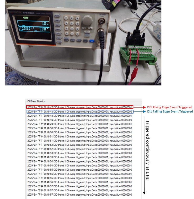
Here we recommend using the DI event callback function, which not only allows you to obtain the DI status but also dynamically monitor DI changes.

To capture DI events, please make sure to set the DI Event Mode to Both (Rising and Falling edge triggered).

P.S. For details on the related library functions, please refer to the SDC development document 'SUNIX IO Expansion Card SDC API for Windows Development Manual_VX.0 For Driver X.X.X.X.pdf'.
5. Result
Dry Contact: Digital Output Signal observed correctly.

Wet Contact: Digital Output Signal, AMPL:10.000V_PP OFST:5.00V FREQ:1.0Hz.
SDC DIO Series: Testing Method for Digital Input Dry and Wet Contacts
1. Introduction
In the previous article, I explained how to test the DO function without any external devices. This article continues from the last one and explains the testing methods for DI. Since DI is a passive receiver of external signals, it always requires an external device to provide the signal. The signal can be supplied in two ways: Dry Contact and Wet Contact.
2. Key Point
Dry Contact
Also called a potential-free or volt-free contact, as the term 'volt-free' suggests, the input itself carries no voltage. It is merely a simple switch that requires either manual or mechanical actuation for operation. Typical applications include door magnetic switches, relay contacts, and push-button switches.
Wet Contact
The signal is voltage-bearing. Unlike a Dry Contact, a wet contact is electrically powered and delivers an active signal directly to the receiving device. Typical applications include PLC output, Sensor NPN/PNP output.
3. Wiring
Here, we take DI1 of the SDC0880I, Dry Contact output source: Push-Button Switches, Wet Contact output source: Signal Generator, as an example.
SDC0880I Pin Define:
- Dry Contact
- Wet Contact
- PNP
- NPN
For SDC DIO Wet Contact, the voltage range for Logic 1 is 10–50 VDC, and for Logic 0 is 0–3 VDC. Applying voltages outside these ranges may result in malfunction of the DI function or even cause permanent damage to the product. Please refer to the SDC DIO Series Product Specification for detailed requirements.
4. Implementation
DI Event Callback Function
Here we recommend using the DI event callback function, which not only allows you to obtain the DI status but also dynamically monitor DI changes.
To capture DI events, please make sure to set the DI Event Mode to Both (Rising and Falling edge triggered).
P.S. For details on the related library functions, please refer to the SDC development document 'SUNIX IO Expansion Card SDC API for Windows Development Manual_VX.0 For Driver X.X.X.X.pdf'.
5. Result
Dry Contact: Digital Output Signal observed correctly.
Wet Contact: Digital Output Signal, AMPL:10.000V_PP OFST:5.00V FREQ:1.0Hz.


