


SDC DIO Series: How to Measure Digital Output Voltage without External Devices
1. Motivation
Many SUNIX customers, when using our SDC DIO series products, often do not have testing equipment at the beginning and attempt to measure the DO voltage directly with a multimeter to verify its functionality. However, due to incorrect measurement methods, they frequently contact us for clarification. This article provides practical measurements and explains the correct operating procedure for this issue.
2. Tip
SDC DO will not function under no-load conditions, so of course you won't be able to measure any voltage changes. Therefore, you need to add an additional resistor as a load during measurement.

3. Software DO Control
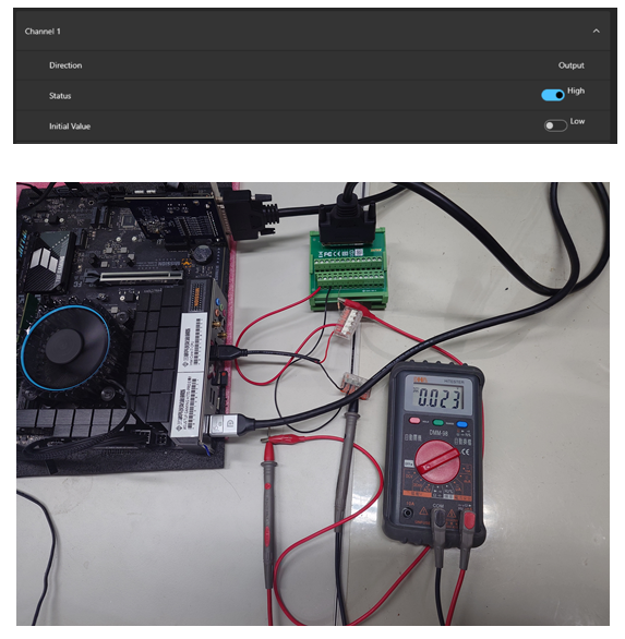
SUNIX SDC Manager provides a built-in DIO control utility, allowing you to toggle the DO pin between High and Low during testing.

4. Wiring
Here, we take DO1 of the SDC0880I as an example with a 5V power supply.

| Step | Connection Description |
|---|---|
| 1 | Connect +5V to DO PWR and GND to DO GND. |
| 2 | Connect a resistor between DO1 and the +5V power supply. |
| 3 | The multimeter’s positive lead should be at DO1, while the multimeter’s COM, DO GND, and the power supply’s negative terminal share the same ground. |

5. Result
From the attached test video, it can be seen that when DO1 is pulled low, the voltage is 5V, and when it is pulled high, the voltage is nearly 0V.
- DO1 Pulled Low, 5V

- DO1 Pulled High, 5V
SDC DIO Series: How to Measure Digital Output Voltage without External Devices
1. Motivation
Many SUNIX customers, when using our SDC DIO series products, often do not have testing equipment at the beginning and attempt to measure the DO voltage directly with a multimeter to verify its functionality. However, due to incorrect measurement methods, they frequently contact us for clarification. This article provides practical measurements and explains the correct operating procedure for this issue.
2. Tip
SDC DO will not function under no-load conditions, so of course you won't be able to measure any voltage changes. Therefore, you need to add an additional resistor as a load during measurement.
3. Software DO Control
SUNIX SDC Manager provides a built-in DIO control utility, allowing you to toggle the DO pin between High and Low during testing.
4. Wiring
Here, we take DO1 of the SDC0880I as an example with a 5V power supply.
| Step | Connection Description |
|---|---|
| 1 | Connect +5V to DO PWR and GND to DO GND. |
| 2 | Connect a resistor between DO1 and the +5V power supply. |
| 3 | The multimeter’s positive lead should be at DO1, while the multimeter’s COM, DO GND, and the power supply’s negative terminal share the same ground. |
5. Result
From the attached test video, it can be seen that when DO1 is pulled low, the voltage is 5V, and when it is pulled high, the voltage is nearly 0V.
- DO1 Pulled Low, 5V
- DO1 Pulled High, 5V


